Author Topic: Calibration guides  (Read 179854 times)

Offline cliffb75

  • Global Moderator
  • Full Member
  • *****
  • Posts: 167
  • BHP: 10
Calibration guides
« on: April 17, 2007, 09:01:27 pm »
Hi All

Right then. I've made a start on the calibration guides. These are based on my experience, and reflect my understanding of the subject and the way I do things. They may not be the definitive solution, and there may be alternative methods, however these work for me.

Please note, I take no responsibility for anything you do with your car when using or following these guides. If you damage the engine or hurt yourself, or do anything else that you or other people don't like, please don't come crying to me. If you are unsure of your ability to map your car then seek professional assistance.

Right then, that the legal bull out of the way - lets  get the first guides up. I'll add more as/when I get around to writing them. In the meantime post any questions and I'll try and help if I know the answer. :)

Cliff

Offline cliffb75

  • Global Moderator
  • Full Member
  • *****
  • Posts: 167
  • BHP: 10
Re: Calibration guides
« Reply #1 on: April 17, 2007, 09:05:12 pm »
Engine Basics

Introduction
Before calibrating an engine, it is first useful to have some concept of what you are trying to control. The following is a fairly brief overview of the internal combustion engine, which will hopefully give you a basic understanding of some fundamental principles and terminology, so that when you change a number in a box on your laptop, you have some idea of the effect it is having on the engine.

We’re assuming that you will be working on spark ignition petrol engines (not those dirty truck engines that run on oil) and obviously running with full engine management (no carbs or distributors here thank you).


The 4-stroke Cycle
First we should cover the fundamentals of the engine itself, in order to understand why we will make particular choices during the calibration process. A piston engine is basically an air pump. In the case of the four stroke cycle (which is now by far the most common) it requires 2 revolutions of the crankshaft to complete 1 engine cycle.


Also see: http://en.wikipedia.org/wiki/Four-stroke_cycle

Since useful work can only occur during combustion on a downward stroke, this has a maximum 180 degree window of effectiveness, meaning the other 540 degrees (at least) of the cycle are concerned purely with removing combustion products, introducing fresh charge and preparing it for the next combustion. All of these phases are using energy, so you can see it is important to both maximise combustion and its timing to get the best out of that 180 degree window, and minimise the losses of the other 540 degrees if the most torque and power are to be achieved at the flywheel.

Volumetric Efficiency
This is a measure of how well the combustion chamber has been filled with air during the intake stroke. If we have a 4 cylinder, 2 litre engine, each cylinder will be 500cc’s. So if during the intake stroke we manage to draw 500cc’s of air into the combustion chamber before the inlet valve closes, we have 100% volumetric efficiency. If we have introduced the correct amount of fuel and we ignite it at the right time, then we will be making maximum torque for that cycle.

As with most things it is not that simple however. Because of the wide range over which an engine must work, it is not easy to achieve 100% VE at all engine speeds. Items such as cam profiles, cam timing, inlet losses and exhaust backpressure conspire to reduce the VE, so that in most cases something more like 75% at low speeds rising to 90% at high speeds is more common, and this is tuned based on the engine requirements

Throttling
Ok, so we now know how to make full power, but we don’t want that all the time. Sometimes we only need enough power to overcome engine friction (idle) or drive along quite slowly (cruise). In these cases we need to restrict the amount of air entering the cylinder - reducing the volumetric efficiency - and we do this using a throttle. This is a pretty simple device consisting (usually) of a circular flat plate (called a butterfly) mounted to a spindle that can rotate in a suitably round housing. By closing the butterfly we can almost stop the air being drawn into the cylinder - the pressure loss across the throttle creates a vacuum on the cylinder side, so less air is available to be burned.

Charge Density
Actually, volumetric efficiency is a bit of a misleading term, because as it turns out, the volume of air trapped in the cylinder isn’t that important. For one thing it’s constantly changing – the piston rising reduces the cylinder volume. But we have trapped the air, so what’s going on?

It’s mass of air we are concerned with, which is related to the charge density. Density is a measure of the mass of something for a given size. So lead is denser than aluminium for example – it’s heavier for a lump the same size. Now the nice thing about air is that it is compressible – that means we can change its density quite dramatically. Think about a hot air balloon. It manages to float by reducing the density of the air trapped inside the balloon relative to the air that is outside of the balloon. Hence, it’s able to rise upwards, and even to carry an additional mass of basket and people.

Now in the engine we want the opposite effect. To get more power we need a greater mass of air, and from the example I’ve just given, you can immediately see that one way to do this is to keep the incoming charge air as cold as possible, to keep the density as high as we can. Another thing we can do is ensure that we keep as much of the original air pressure as possible as the air comes into the engine through the filter, along the inlet ducting, past the throttle, through the plenum, down the ports and into the combustion chamber. So for our 500cc cylinder, to achieve 100% VE, we need to trap the equivalent mass of air as we would get in a 500cc cylinder at the temperature and pressure of the ambient air outside of the engine. Just for interest, the density of air at 20 C and at sea level is approximately 1.2kg/m3, so our 100% VE means that for a 2 litre engine we are burning just 2.4 grams of air per cycle.

But what if we want more torque from our engine? Then we need more air, and to get this we have some choices. We can increase the engine capacity. Or we can increase the VE above 100%. How? Well in very highly tuned naturally aspirated engines we can use ‘pulse tuning’ or ‘ram tuning’ effects to get maybe as far as 105 or 110% in a very limited speed range, but if we really want to make torque from a given capacity we need to boost it.

Forced Induction
Boosting, (or pressure charging or forced induction) is generally achieved by either supercharging or turbocharging. The difference is in the way the devices work, but they both do the same job – they compress the air entering the cylinder to higher than atmospheric (barometric) pressure, allowing more air to be forced into the cylinder. By changing the size and type of pressure charging device we now have almost free reign of over the volumetric efficiency. Need more air? – just turn up the boost!

Well not quite. Like most things there is a downside, and first is heat. When you compress air is gets hot. And we know that when air gets hot, its density drops, and so for a given volume you now have less mass of air. The extra heat also increases the chances of detonation, which we will cover in the Ignition section, but as you will find out, this is a bad thing. So in order to counteract this increase in charge temperature, we fit some kind of intercooler or charge cooler.

An intercooler is basically just a heat exchanger that passes the hot inlet air through a matrix where it can lose heat to another medium – usually air (an air to air intercooler), or water (an air to water intercooler, or sometimes called a chargecooler). Depending on the size and efficiency of the intercooler it can drop air temperatures at the compressor outlet from over 100C to near ambient temperature. But again there is a price to pay. Introducing this additional pipework and matrix to the inlet tract increases pressure losses (meaning we need an even BIGGER turbo) and introduces additional volume between compressor and cylinder. The bigger this volume is, the more lag we will experience, i.e. the time between pressing the throttle and the engine receiving the additional air, as that large volume of air has to be compressed. It’s a bit like watching one of those NCAP car crash tests on TV where the car starts to crumple at the front bumper and gets progressively squashed as it goes along. The air in the pipework is behaving in the same manner. 

The other slight snag with forced induction is matching of the turbo or supercharger to the engine. These devices are only capable of operating properly in a certain range. Outside of this they become inefficient, adding huge amounts of heat to the air for small increases in pressure, or even become incapable of supplying boost due to the turbine stalling, or more air due to the outlet becoming choked. Therefore the chosen device must be specified with the final engine requirements in mind in order to get the desired performance. This is too big a subject to cover here, but you must bear this in mind when attempting to get more performance from your standard engine. Usually you can turn up the boost a bit before new components are required – but there are limits!

Combustion
So now we have managed to cram the greatest amount of air into the cylinders, we need it to go bang. Combustion comes by mixing oxygen (air) and fuel with each other, and then igniting the mixture. You can achieve combustion under a wide range of conditions, but the best combustion will occur when you have a well mixed quantity at the correct ratio of fuel and air. As we will see later in the fuelling section, the definition of ‘best’ can vary depending on other requirements (power, economy, engine life). This mixture ratio is known as the Air Fuel Ratio (AFR). The condition when all the fuel and all the oxygen are consumed during combustion is called the stoichiometric AFR, and is around 14.7 parts of air to 1 part fuel for a gasoline engine. Note that we measure the ‘parts’ in units of mass. To normalise this AFR we can convert it to a value called Lambda. This is simply the current AFR / stoichiometric AFR – so at stoic, we are at 14.7:1, which is Lambda = 1.

When we then put that mixture, also known as the charge, into the engine we must also consider where in the cycle we want it to start burning. Again there is a wide range of ignition timing that will allow the engine to run, but the best conditions will be when the timing is in one critical region. As with the fuelling, we will see that this is not fixed for all conditions, and depends on the same factors listed above.

The quality of combustion directly affects the torque output of the engine. The aim is to get the highest mean (average) cylinder pressure during the useable expansion stroke, and to do this we need the charge to ignite well, burn reasonably quickly and burn completely. By minimising the ignition phase we increase the time available for the burn. By ensuring the combustion is complete we do not waste any of the air that we struggled to get into the cylinder. (Note that fuel is less of an issue here, and additional unburned fuel is better than unused air. See the fuelling section.)

 It is important to remember however that combustion is a burn and not an explosion. The internal parts of the engine cannot cope with excessively high pressures and temperatures that explosions would produce (which is why detonation is to be avoided – see the ignition section), so there is a balance to be struck between fast and too fast a burn. This in turn depends on the speed at which the engine is intended to rev – a high revving (over 15000rpm) motorcycle engine will need to have a combustion system that is significantly faster burning than say a moderate revving (6000rpm) standard road car engine, simply because at over twice the speed there will be less than half the time available to do the same work.

Compression Ratio
The static compression ratio is simply the ratio of the cylinder volume when the piston is at the bottom of the cylinder (Bottom Dead Centre or BDC) and the top of the cylinder (Top Dead Centre, TDC). The compression ratio has a strong bearing on various factors including charge preparation, combustion, and thermal efficiency.

Up to a point a high compression ratio is good. As the piston moves upwards it compresses the charge, moving it around and helping with mixture and fuel vaporisation. With the higher initial pressure, the peak cylinder pressure from combustion will be higher, and the charge will burn better and quicker, which in turn means it will lose less of its heat to the cylinder walls and piston crown.

However, increase the compression ratio too much and there are problems. Extra heat is generated during the compression stroke, and it takes more effort to compress the mixture. When combustion starts it burns too fast or promotes detonation or even pre-ignition.

So there is a balance to be struck. Unfortunately the correct compression ratio for one speed / load condition is not the same as for another. Current OEM’s tend to set the compression ratio to be slightly high at peak torque, since it brings improvements in the part load conditions that most normal cars spend the majority of time running in.  When choosing / developing you compression ratio, you need to be realistic about what you want your engine to do. If peak power is the main requirement than a slightly lower CR may be of benefit, but will cost you more in fuel during part load running. If you’re building a road car however, you may wish to use a higher CR to keep the part load response and fuel economy benefits, but you need to accept that you are compromising on full load performance.

Also remember that the type of fuel you intend to use affects your decision. If you wish to use cheap 95RON pump fuel you will need a lower CR than if you only ever run 102RON race fuel. But as we will see in the ignition section, you must be clear about these choices up front, and be prepared for extra work if you change your mind later.

Valve Timing
At first glance, it may appear obvious what the valve timing and duration should be. For the inlet valve, open it at the top of the induction stroke, and close it at the bottom. Same idea for the exhaust (open at the bottom close at the top) right?

Well, by now you are starting to see that it’s never that simple. What we have to remember here is that the air has mass, and if it has mass then it has momentum. Momentum is ‘the tendency of an object to continue moving in its direction of travel’, or to put it another way, a reluctance to change velocity. When the inlet valve is closed, the air in the port is stationary. So when the valve begins to open, the air will not instantly rush in. It will move slowly at first, accelerating as the pressure difference across the valve exerts a force on it. Towards the end of the induction stroke, the air will be happily rushing in as the valve closes and it is forced to stop. Therefore, if we open the valve earlier, and close it later we can counteract the intial sluggishness, and make use of the final momentum to increase the amount of air we get into the cylinder.

Now we have already calculated how much air we will be trying to draw into the cylinder for each cycle – but as engine speed increases, the amount of air we try to draw in per second will increase. Therefore the momentum of the air will need to be overcome / utilised by increasingly long duration valve timing. But I think you can see where this is leading – if we increase the duration to cope with high speeds, it is too long for low speeds, and vice versa. This is exactly the compromise engine development engineers have to make. This is again where we need to make our choices about what we expect from the engine in advance. Do we want all out power at the expense of idle quality and mid-range torque? Or are we willing to sacrifice some horsepower at maximum revs for a bigger torque curve lower down the engine speed range? Only you can make that decision for your engine. Of course if your engine is equipped with VVT (which may come in anything from two point inlet only to fully variable inlet and exhaust control) then this is one more thing you can optimise from the comfort of your laptop, but be prepared for lots of time on the dyno to find the best settings.

As far as valve lift, cam profiles and valve overlaps are concerned, this is again too big a subject to cover here. Refer to your favourite engine tuning books for more information. I’d recommend those by A Graham Bell as a very good starting point.

Summary
This is by no means an exhaustive explanation of the internal combustion engine, but I hope it has given you a first glimpse into the complex world of compromises that are required when developing an engine. When calibrating the engine management system, you are looking to try and make the best use of the engine as its is presented to you, and at times it may seem that there are obstacles being placed in you way that prevent you from achieving better performance.

But remember, if it is your engine, you can choose to change those compromises! So when you are calibrating, consider the engine hardware as an extension of the process, and don’t be afraid to make a change if you feel it’s needed. Hopefully you will end up with the engine performance you want, rather than just the best performance you thought you could manage.


Offline cliffb75

  • Global Moderator
  • Full Member
  • *****
  • Posts: 167
  • BHP: 10
Re: Calibration guides
« Reply #2 on: April 17, 2007, 09:14:50 pm »
Ignition

For the DIY engine calibrator, ignition mapping appears to be the most overlooked area of work. The reasons for this appear to be two fold – it is a misunderstood (or indeed completely not understood) area of the engine control, and it is difficult (read expensive) to setup properly. Hopefully this section will cure the first of these problems, but I’m afraid I don’t have a simple solution for the second.


Ignition Timing Theory
In the engine basics section we briefly covered the changing requirements of ignition timing across the speed load range of the engine. Let’s look into this a little further.

We’ll assume for now that for a given condition we have the ‘right’ amount of air and fuel (‘right’ being a relative term depending on the conditions – see the fuelling section). In which case we then want to ignite whatever charge we have managed to trap in the optimum manner to make the best use of it. If we ignore the idle region for now (we’ll come back to that later, as it is a special case) this normally means finding the ignition timing that makes the most torque for the given charge. As usual it’s not that simple however.

The topic of combustion is very complex, and far too large to cover here, so I will only give a very brief overview. It’s important to remember that combustion is a burn of the charge, which starts at the spark plug and then travels out towards the edge of the combustion chamber. Therefore the combustion process takes a finite amount of time – it’s not instantaneous. There are many factors that affect combustion – chamber shape, chamber size, air fuel ratio, mixture preparation, compression ratio, squish, port design……you get the idea. In order to make the most torque from the engine, we need to make sure that the main part of the burn occurs when the piston is just starting to travel back down the bore. Too early (advanced) and the burn will actually slow the piston down as it rises to the top of the bore. Too late (retarded) and the piston will be too far down the bore before the burn gets going. The end result is that because under some conditions the charge burns slower than under other conditions, and because combustion does not speed up as the engine speeds up, we need to start the burn earlier or later in order to make the most of it.

To understand what it going on during combustion, engine developers fit pressure sensors into the combustion chamber. They then use an encoder to measure the cylinder pressure every 0.1 degrees of crankshaft rotation. The cost of the equipment to do this is only slightly less than the average British house price, so it’s not something I need to cover in detail here. From the data collected they can then calculate a lot of useful stuff about the combustion process – none of which you really need to know here either. However, from this data it is also easy to set the correct ignition timing, and a picture shows you why.


When looking at cylinder pressure against crank angle, it is clear to see the effect of changing the ignition timing. Too advanced and we get too high a cylinder pressure, and too much area is before TDC. If we are unlucky (which we often are) or aggressive enough, we can also get knock. With the right amount of ignition advance we get the best balance of combustion before and after TDC, and with retarded ignition we get very little useful work as the pressure simply does not rise enough. From that I hope it is clear why ignition timing is so important to get right.

Knock (detonation) and MBT
For most engines setup with a sensible compression ratio, and certainly for forced induction engines, we end up dividing the speed load map into 2 basic areas – MBT limited, and knock limited. But what do these terms actually mean?

MBT
MBT (Minimum advance for Best Torque) is the normal operating mode of the engine. This is the ignition advance setting that you should strive for unless you become detonation limited. If we were to use an in cylinder pressure measuring device (which we won’t because they are really very expensive) we would find that generally MBT equates to the peak cylinder pressure occurring around 12 degrees after TDC, or even more accurately, when the 50% mass fraction burned (i.e. when we are halfway through combustion) occurs at around 8 degrees ATDC. Because the flame speed varies with various factors, the time at which we ignite the charge changes for speeds (earlier with higher speeds) and load (later with higher load) so that the best bit of the burn remains in the right place. If we move the ignition timing either side of this optimum timing the torque drops. It just so happens that the manner in which it does this, when expressed as a percentage of the optimum torque, is pretty repeatable across the speed and load domain, and this leads to the ignition efficiency curve


So, if you were to perform a spark sweep (i.e. change ignition timing in 2deg steps from advanced of optimum to retarded from optimum) with everything else fixed (speed, throttle position, lambda, inlet temperatures etc) this would be the resulting torque as a percentage of the maximum torque seen at that condition. Remember this is fixed load – the air and fuel being used don’t change. The change in torque is purely down to how effectively we burn that air and fuel. The generic curve is produced by running spark sweeps at a large number of speeds, loads etc and then taking the average. In a modern production EMS this curve is then used as part of the torque control system to help control the engine during torque down requests (e.g. auto trans gearshift), idle and so on.

The eagle eyed among you may have noticed that around the 100% efficiency the curve is quite flat – there is very little change in torque for quite a large (maybe 10 degrees) change in ignition advance. This is where the ‘Minimum’ bit comes in. Normal practice is to set the ignition timing on the retarded side at the point where the torque just begins to drop – e.g. the 99.5% point. This is the best for the engine as it produces the most torque for the least peak cylinder pressure.

I've also added an example of EGT increase with retard from MBT. The curve shape is a bit like the inverse of the efficiency map (not a surprise really), so the further from MBT you are the greater the temp increase. Those numbers are NOT generic though so make sure you measure it yourself. Its not a one size fits all curve.

So the ignition timing at which you get the most torque is MBT. This is the ignition timing we are aiming for over most of the map. But at higher loads towards WOT, or for lower RON fuels, higher inlet temps etc we run into knock before we are able to reach the MBT point. This is known as being 'det limited'.

Knock
Knock occurs when the mixture in the combustion chamber self ignites before the spark ignited flame front reaches it. This results in a collision of the two rapidly expanding flame fronts, and hence a high pressure wave is formed, which sounds like a 'ping'. The flames themselves are also very high speed, due the conditions being severe enough to cause knock also being good for promoting rapid combustion.

The more extreme form of knock is Pre ignition where the mixture self ignites before the spark has even occurred. This is particularly damaging, and generally engines don't last very long if they are driven into PI.

Also, knock does not necessarily begin in just one place within the combustion chamber. Severe knock may have multiple initiation points, and if you are unlucky enough that they collide at the same point you get a pretty big PING.

Knock is not a fixed event. It varies in intensity and does not occur every cycle (until we get to a level of knock that will quickly destroy engines). However, it can be self perpetuating, leading to a condition called ‘runaway det’, which is basically pre-ignition. This will quickly kill your engine.


There are many factors that affect knock – compression ratio, charge temperature, combustion chamber design, fuel octane (RON), humidity, and so on. You can help reduce the likelihood by building your engine correctly, but by the time you get to mapping all you can really do is richen the fuelling (cools the charge, hence reducing knock tendency) and retard the ignition timing. If (usully for boosted engines) neither of these things works, i.e. you are running so retarded that you get EGT’s that require so much fuel that you get misfire/ excessive black smoke, and its still knocking – then you will have to reduce the load. Then it is a case of looking at your engine or installation to improve things to reduce the chances of knock (better intercooler, lower compression ratio), and try again.

So now we know about combustion, we know about det and MBT – its time to start mapping right?

Well not quite yet. There’s one last thing I want to tell you about, and that’s the bits that make the sparks.

Ignition Hardware
In the (good?) old days before engine management, ignition timing was controlled by a distributor. Even at the peak of their development, these were a crude device, subject to all sorts of inaccuracies and problems. As we mentioned, the ignition timing requirements vary according to the speed and load of the engine. Although distributors allow some compensation for this, via springs and bob-weights for speed, and a pressure canister for load compensation, these are effectively linear response actuators.

However, the engine is not a linear system (vagaries such as ram tuning effects and resonances take care of this). Hence tuning the advance curves of a distributor is a further compromise that must be made. With an engine management system, this compromise is eliminated. With a 3D mappable system we can set the optimum spark advance under all conditions to ensure we get the best performance

In order for the engine management system to work we need some (fairly accurate) information. We need to know the engine speed, the engine load, but also the engine position, i.e. where TDC is. Load is taken care of by either MAF, MAP or TPS sensors which I won’t cover here, other than to say it doesn’t matter which system is being used the principle is the same – they simply tell you what part of the load axis the ignition map needs to look up to read off the correct ignition angle. More importantly, the engine speed and position are taken care of by engine position (crank and cam) sensors.

We can use all sorts of arrangements for engine position sensors. Distributors, cam mounted wheels, front pulley mounted or flywheel mounted items have all been used, with as few as 2 teeth and as many as 360. Possibly the two most common and easily found trigger wheels are now the Bosch 60-2 and the Ford 36-1 arrangements. The numbering refers to the number of teeth; 36-1 means it would have 36 teeth, but one has been removed, resulting in 35 teeth and long gap.


Typically Ford mount their wheels on the front pulley and are therefore reasonably small in diameter, whereas Bosch systems mount theirs on the flywheel or flex-plate and are therefore quire large.

In reality for aftermarket systems we don’t need this many teeth. The requirement for this level of accuracy comes from the OBD (On Board Diagnostics) and emissions requirements that modern car manufacturers must achieve. For an aftermarket type ECU, 4 teeth per revolution is plenty accurate enough. However, as in most cases, it will be a case of what you can find that fits.

To go with the trigger wheel you will need a sensor. There basically 2 types – inductive and hall effect. The basic difference is that Hall effect sensors require a power supply and work really well. Inductive sensors don’t require a supply, but are more sensitive to installation (air gaps) and signal noise. Given the choice, I’d use hall effect every time, as they give a cleaner, more robust signal.


Whatever method you use to control the timing of the spark, you will still need two other items – a coil (or coils) and spark plugs. There isn’t much to calibrate in a spark plug other than the heat range, and typically for a modified engine that is simply a case of choosing a plug one or 2 grade colder than standard depending on how much you have increased the power of the engine. There are however a few things you should know about coils.

An ignition coil is basically a transformer – it takes low voltage and turns it into high voltage through the miracle of magnetic fields and stuff. How much voltage come out of it is a factor of 2 things – how much voltage went in and for how long. The amount of time we hold the coil energised is called the dwell time. For a given battery voltage we need a minimum dwell time in order to get sufficient energy in the coil to make and sustain a spark capable of igniting the charge in the cylinder. Straight away we can see therefore that we need to compensate the dwell time for battery voltage in order to get the required spark energy.

This is where it starts to get tricky. The required spark energy changes according to the conditions in the combustion chamber. A homogeneous (fully evenly mixed) stoichiometric (lambda = 1) charge requires around 0.2mJ of energy to be stored in the coil for a sufficient spark event to ignite it. However, as mixtures get richer or leaner, or charge becomes insufficiently mixed (resulting in local lean pockets near the spark plug), this requirement can increase by up to 10 times.

The spark event itself is not instantaneous, but is of a ‘peak and hold’ nature, requiring a very high initiation voltage (around 30kV) to begin the spark, but quickly dropping to sustain the spark. In total, spark duration may be from around 0.5 to 1.5 ms (depending on ignitability of the charge) in order to ensure good ignition.


So to get the required energy (to both start the spark and sustain it long enough for the charge to ignite) we need to make sure we have a long enough dwell time. So why don’t we simply charge the coils all the time unless we are sparking? Well, the problem is that when you pass electricity through things they tend to get hot (just look at lightbulbs and electric heaters). It’s the same with coils. If we were to leave them energised all the time, they would quite quickly overheat and burn out. Therefore running with excessive dwell times shortens the life of the coils. For car manufacturers they need to be careful about this (to avoid warranty claims and unhappy customers), but fortunately we can be a little less concerned, which gives us a bit more leeway.

The combined effect of this is that we need to vary the dwell time with these conditions in order to ensure we get a good spark. Take a look at the example below


The reason for this non linear shape is that two effects are being compensated by one curve. The first is battery voltage, which would normally be a (roughly) linear effect. However, we normally see low battery voltages during cranking and starting. This is also the time at which we have poor charge preparation, rich mixtures and low speeds, all of which make it more difficult to ignite the charge. Hence there is an extra compensation included in the single curve that covers these conditions, and helps things along.

Once the engine is up and running we find another problem – available dwell time. Each cylinder requires one spark every 2 revs. The spark itself takes around 1ms. So that leaves an amount of time for dwell. At low speeds this is no issue, but at higher speeds on multi cylinder engines, it can be a problem.


You can see from the chart that there will be maximum engine speeds dictated by the available charge time and the requirements of the coil. For example, if your chosen coil requires a dwell of 2ms per fire then for a V8 with a single coil you will not be able to supply sufficient spark energy over 4300rpm, and misfires will be the result. Make sure you check that your intended coil will actually work in your installation before you part with any hard earned for it.

So that’s all (that I can think of at the moment) of the background and theory. If you’re still with me at this point then well done. Having been through all that we know we need to map the ignition timing map properly – so, at last! how do we set about it.

Offline cliffb75

  • Global Moderator
  • Full Member
  • *****
  • Posts: 167
  • BHP: 10
Re: Calibration guides
« Reply #3 on: April 17, 2007, 09:24:26 pm »
Ignition, continued

Preparing for Ignition Mapping
Unfortunately, the only way to truly find the optimum ignition timing under all conditions is to use a dyno – either an engine dyno or a rolling road. In most cases an engine dyno is quicker during the actual mapping phase, and more accurate and repeatable, but it is also generally much slower on the installation phase, and has other problems such as being unrepresentative of the actual engine installation (temperatures, exhaust systems etc), so compensations are often required when the engine is fitted to the vehicle. However, for full engine development (where engine hardware is being developed at the same time as the calibration), engine dyno’s are the way forward.

For most DIY engine calibrators however, this isn’t an option. So we rely on the chassis dyno, or rolling road.

Before we charge headlong onto the dyno, strap the car down, fire up the laptop and start peddling, it’s worth spending a little time making sure we and the car are prepared.

If you’re going to map the car, you will obviously need to be able to talk to the ECU. So a laptop, cable and the right software will be needed. Make sure you test this all out before hand and become familiar with it so that you don’t spend valuable dyno time looking for the right map or working out why it won’t upload software. You will most likely have done this in order to get the car running and idling in the first place – make sure that whatever configuration you used then (and was working) is what you take with you to the dyno. This is not the time to discover you new spangly laptop isn’t compatible with your USB to serial cable…….

For ignition mapping you will also need some way of detecting the onset of knock. ‘Det cans’ made from a pair of ear defenders with rubber tube running to them from a piece of tube bolted to the block are one option.

http://www.h-dev.co.uk/article.php?article=17

Otherwise a knock sensor fitted to the engine and connected to an oscilloscope, soundcard and software or audio amplifier and headphones are all viable alternatives. My personal preference is for a knock sensor and scope, as that’s how I learned to do it way back when, but using det cans or headphones is a perfectly reasonable alternative.

It is highly advisable to also have some way of measuring the EGT’s (Exhaust Gas Temperatures). This may be through the ECU itself, or it may be using an external gauge (like the VEMS wideband and EGT gauge). Your thermocouple should be in the collector of the exhaust manifold where it can see the gas from all cylinders. For a V engine you will need one thermocouple per bank. For turbo engines, the thermocouple should be located just before the turbine entry, either in the manifold or the turbine housing. Be careful with the size of thermocouple you use – you don’t want it to fatigue fail and drop into the turbo. Whilst you are not calibrating the ignition map using EGT, you need to know the temperature so that you can add (or remove) fuel as you change the ignition timing at high speed and loads. As a quick rule of thumb, NA cars run to an EGT limit of around 850C, and turbo cars run to a pre-turbine EGT limit of around 950C,  but if possible try to find out what other people have mapped similar engines to yours to and why. It could be that your engine is particularly good / bad and can tolerate more or less heat. Do your homework.

The next thing is to make sure you have the right fuel. You will need a full tank, and it must all be the right fuel, and reasonably fresh. Mixing half a tank of old 95RON with a splash of 98 on the way to the dyno isn’t going to cut it.

Higher RON fuels will mean you are less det limited, which is why you map on the fuel you intend to run. But for our stuff which doesn't have active knock control (or at best has a fairly crude system just to protect the engine), be realistic - if you are normally going to use (cheaper) 95RON and drive it through the summer then get it mapped in that condition. Yes you will be able to get a lot more torque and power by mapping it on 100RON and running with freezing cold air blasting into the inlet, but if you map it to that then the first time it gets really hot and you've filled it with 95RON then it’s piston meltdown time. Of course if you go the other way and map on 95RON you will safely be able to run 98RON – but you won’t get the benefit. However, it will be much easier (and safer for the engine) to advance the ignition slightly in the car than to have to retard it.

Before you leave the house for the dyno, make sure you check the car. Check the oil and coolant are at the correct level and in good condition. Check the hose connections and make sure there are no leaks (dyno operators don’t like fluids dripping into their expensive machinery). Rolling roads are hard on tyres, so preferably take spare set of dyno wheels along, with tyres that are in OK condition. Take a note of the tyre pressures in those wheels – you will need to know this if you wish to return at a later day to accurately see if a modification has improved power. Also give the car a check over for any air leaks – either inlet or exhaust. In order for your mapping to be accurate the car needs to be in good shape, and air getting in or escaping where it shouldn’t will change the engine’s characteristics and result in a calibration that, once the problem is fixed, is no longer optimised.
 
Also remember we will be there for a while – 2 or 3 hours minimum, maybe a couple of days if we have problems. So make sure you have a power supply for your laptop – either and in-car type (and somewhere to plug it in) or a mains supply. If your laptop battery goes flat, that’s the end to your mapping session.

Beginning Mapping
Ok, so we’re completely ready. The car is in perfect shape, we’ve got a full tank of the right fuel, a fully charged laptop and bags of enthusiasm. Its time to start putting numbers in boxes.

Setting the Reference Angle
The first thing we need to do is calibrate the reference angle. In most cases we would do this before we get to the dyno. The number you need in the box is all going to depend on how you set your system up, but basically this is the angle between when the reference tooth passes the crank sensor, and TDC. Now depending on your setup, the reference tooth can be selected as any tooth after the missing tooth. This is commonly set to the first or second tooth (depending on how many you have to start with), and where your missing tooth is located in relation to TDC cylinder 1. Typical value for the reference angle is 60 degrees before TDC – i.e. the sensor sees the reference tooth pass by, and 60 degrees later the engine arrives at TDC on cylinder 1. It needs to be early like this to allow the ECU time to perform the ignition and fuel calculations before they are required.  It’s also important to note that these angles need not bear any relation to the actual angular location of the sensor relative to the engine – your particular installation will need to be assessed and calibrated accordingly.

From experience I’ve found the easiest way to calibrate the reference value is to make a clear mark on the front pulley for TDC cylinder 1 (use a dab of paint on the pulley and pointer so that it stands out).  Put in the approximate value of reference angle (you should be able to measure or calculate this) and get the engine running at around 1500 – 2000rpm. Then use a timing light with an adjustable advance (or set the ignition advance in the ECU to 0) and modify the reference angle until the timing light agrees with the ECU. Even some production engines have a tolerance of +- 2 degrees, so it is worth checking this if you’re looking for accuracy and repeatability.

With this calibrated, you now know that your ignitions advance settings are true angles BTDC, which will help when comparing your calibration to that on other engines, or if you need to calibrate multiple engines.

Dwell
The next thing to check is the coil dwell. The values you require will depend on the coil(s) you use. Check the manufacturer’s specifications. Remember we need a minimum amount of energy to make a good spark but too much dwell can cause the coils to overheat and fail, so try to be as accurate as you can. If you find later that its misfiring slightly when rich or lean, you could try increasing the dwell time. But remember, once you get past that magic energy threshold, any extra dwell is not adding engine power, but is reducing the life of the coil(s).

Calibrating the Ignition Map - Finding MBT
Once you have got the initial settings dialled in correctly, then you know where you stand. This is where it gets difficult. The problem with calibrating ignition advance is that there is no convenient in car sensor that you can buy (like a wideband lambda sensor and EGT gauge for fuelling) that allows you to measure if it’s right or wrong. Also complicating things further is the issue of MBT or detonation limited ignition timing. Ironically, it’s the det limited region that’s easier to set up. Some method of hearing/seeing det (det cans, knock sensor and scope/sound card etc) and you can actually find the ignition limit driving on the road (though I wouldn't recommend it - I'll come to that in a minute). However, you cannot find MBT without some kind of external torque measuring device - a braked rolling road or engine dyno in fact (well, thats not quite true, but the other methods for finding MBT are too expensive to mention here, so dyno it is).

The easiest way to get up and running is to swipe a map from someone else with a similar spec engine. If this has been mapped reasonably well, then it may be a good starting point for your engine too. For all engines, similar means using the same fuel type (the difference between 95RON or 98RON can be up to 6 degrees difference to mapped ignition). When using a MAF based system, a similar engine means same MAF meter. When using MAP system, similar engine means (at least) similar capacity, similar compression ratio, similar cams and similar exhaust backpressure. For TPS add throttle size to this list too. This is because the correct ignition timing is related to air mass, so the conversion from manifold pressure or TPS to air mass flow will depend on your engine spec - i.e. the things listed above.

So a note of caution. WHEN COPYING AN IGNITION MAP FROM ANOTHER ENGINE BE CAREFUL! If your engine flows better than the donor map engine then you will be getting a higher load for a given manifold pressure. THIS COULD LEAD TO YOU DAMAGING YOUR ENGINE If you are not extremely careful to listen for detonation.

Now you have something that runs (maybe even seems OK) its time to get on to the dyno. In order to calibrate the ignition map you need to perform spark sweeps (or loops) at fixed speed and load point. This is why you need a braked dyno e.g dyno dynamics, as it will hold the engine to a fixed speed regardless of how much load (MAF, MAP or TPS are your load measurement) you put on the engine. You cannot do accurate spark mapping on an inertia type dyno. You will also find it useful to have some kind of adjustable throttle stop (or stops) - little blocks of wood of different sizes will do - that allow you to easily hold a fixed throttle position. Ideally you would run exactly on a map site, but since that is unlikely you may wish to ‘block map’ (i.e. enter the same value in several sites) the area around where you are working to be able to set the ignition timing accurately. Once you have the car running at a fixed speed/load (start at low speed and load as its safest for the engine and will give you a feel for what’s happening), you then need to sweep the ignition in 2 degree steps and record the speed, load, ignition advance and torque figures for processing later offline. The ignition advance that gives you the highest torque is TRUE MBT. You will notice (if you plot the data) that the curve is very flat at light loads. MBT is Minimum ignition for Best Torque - i.e. it is on the retarded side of the curve. So standard practice is to then set the map value to slightly retarded of true MBT, e.g. the point at which the torque has dropped by 0.5% from peak when plotted.

Follow this process and slowly fill in the map from low speed low load working diagonally up the speed and load axes - using the blocks of wood method, moving up the speed axis before changing load will be quickest as it is easy to change the dyno speed. If you are just using you foot to hold the load then moving up the load axis before changing speed will be more comfortable. Whichever way you do it, remember to be listening for knock before you get any so that you can back off the load. You don't have to map every site, but since there aren't that many sites in VEMS (which is a good thing), it wouldn't take too long if you did. Your biggest problem will be aligning your data with your axis breakpoints - if you are using the 'blocks of wood' throttle stops you may need to do some interpolation (smoothing) of the data points. Take the data you have recorded and process it using Excel to adjust the values to the correct map breakpoints. Then put these values back in the map. Make a quick check by running at a few of your previous sites, and confirm that you get the same torque (within repeatability limits) as you did when mapping. Once you’ve been through the process once or twice you will get a feel for it, and things will speed up considerably.

At some stage you are likely to become det limited, i.e. the engine will begin to knock before you reach MBT. Remember you need to have a knock detection system in place and working before you get to this point.

Calibrating the Ignition Map – Finding DET
This is the scary one, but ironically it doesn’t necessarily need the expense of the rolling road. However, as with finding MBT, the best way to map the det limited area is by performing a spark sweep from retarded up to the det limit. Knock is most likely at low speed/high load sites, and then will decrease in strength as you increase the speed. This is because of the way in which knock occurs – low speed mean the piston stays around the top of the bore for longer keeping the temperature and pressure high, which increase the chance of det.

So how do you know what det looks or sounds like? The first thing to remember is that det isn’t a fixed on or off. Just as combustion is variable, so is the intensity of knock. It ranges from very light click every so often to repeated tap tap tap.
When the engine is knocking, this also has a tendency to promote further knocking, as the sharp increase in combustion chamber temperature doesn’t dissipate before the next cycle. At it most severe this can lead to a self defeating cycle known as ‘runaway det’, and the only way to stop this is to back off the throttle, and then take a few degrees of ignition out before putting the load back in and trying again.

The next thing to remember is that det does not occur every cycle (until it gets to engine damaging levels). This is useful, since the human brain is very good at recognising patterns. You will find with whatever method you use to detect knock that there is a lot of signal noise for the engine – valves opening and closing, combustion noise etc. However these noises will be there every cycle, whereas the det signal will come and go in a semi-random way. This should allow you to pick it out above all the other noises you can hear or see. Fortunately for us knock intensity is reasonably well linked to the knock occurrence frequency (i.e. how many knocks we see per second) – so we use this to define the acceptable level.

For an engine without active knock control, I would recommend setting the ignition map to BLD - 3 degrees. BLD = Border Line Detonation, i.e. when you can hear knock occurring and a rate of about 1 'ping' per second. So whatever ignition advance this occurs at, take 3 deg off this and enter that into the map.

Another word of warning. DETONATION IS SENSITIVE TO INLET TEMPERATURE. If you map the engine when the air is cold (i.e. in the winter) you will find it is too advanced (in the det limited region - MBT is less affected) when the air temps get hot. If you are not using any inlet air temperature correction (which should be around 1deg retard for every 10deg increase in inlet air temp in the det limited region) then BE VERY CAREFUL. Turbo engines are even worse for this, particularly when people just turn up the boost and start to run off the end of the compressor map, which introduces a lot more heat to the inlet air.

When you map the high speed and load area, it may be a good idea to do it in short bursts. Keep a good eye (or get someone else to) on inlet, coolant and exhaust gas temps, and don’t let them get out of control. Cars often run quite a lot hotter on rolling roads (as the fans are often on the small side), so be careful.

So, at the end of a day on the rolling road (or maybe less if you're quick / experienced) you should have an ignition map, and by association a fuel map (since you will have needed to be adjusting the fuel throughout in order to get the best torque / keep the EGT's at a sensible temperature). This is now the basis upon which you can develop the rest of your cal for starting, idle and driveability, which we will cover elsewhere.
« Last Edit: April 26, 2007, 09:55:59 pm by cliffb75 »

Offline cliffb75

  • Global Moderator
  • Full Member
  • *****
  • Posts: 167
  • BHP: 10
Re: Calibration guides
« Reply #4 on: May 02, 2007, 11:24:50 pm »
Fuelling Theory
Let’s start with the theory then. We are concerned with spark ignition gasoline engines here. I’m only going to cover gasoline, since Diesel is for trucks and diggers, and alcohol is for drinking and drag racing.

Chemistry
Now you might think that petrol is petrol right – not exactly. You will probably have heard the term ‘hydrocarbons’ before, perhaps as part of the MOT emissions check. Hydrocarbons are raw fuel – they are a chemical compound of hydrogen and carbon. Without getting into too much of the chemistry, there are different fuels, the simplest of which in structure (the alkanes) consist of chains of carbon molecules, each linked with the next carbon molecule and  with two hydrogen molecules. The end carbons then have an extra hydrogen. This leads to a family of fuels with the chemical formulae CH4, C2H6, C3H8 etc. These three examples are more commonly known as methane, ethane and propane.

Now because of the weird and wonderful way in which chemistry works, you can also get different arrangements of atoms, where the structures vary according to which H is bonded to what C, and how strong the bond is. Take for example C7H16. For the same number of C’s and H’s, it can be arranged in four different ways. Why is this important? Because the structure defines their properties as a fuel, and how they are broken down when they burn.

We’re all familiar with the RON value of petrol right? (If not don’t worry, I’ll come to it in a bit). A higher RON means the fuel is more resistant to knocking (self igniting). Well for our example C7H16, n-heptane has RON of 0, i-heptane (2,4-dimethylpentane) has a RON of 83, i-heptane (2,2-dimethylpentane) has a RON of 93 and good old i-heptane (2,2,3-trimethylbutane) has a RON of 112.

Overall a typical gasoline is predominantly a mixture of paraffins (alkanes), naphthenes (cycloalkanes), aromatics and olefins (alkenes). The exact ratios depend on the oil refinery that makes the gasoline, but with ever stricter requirements from manufacturers and government, gasolines from different companies are generally very similar in composition.

As you can imagine, there is a whole lot more to fuels than this, and that is why fuel companies spend a lot of money on research, playing with new blends of fuels and various additives (anyone remember lead) to improve certain desirable qualities. Here are a couple of interesting links to start you off.

http://www.atsdr.cdc.gov/toxprofiles/tp72-c3.pdf
http://www.chevron.com/products/prodserv/fuels/bulletin/motorgas/3_refining-testing/

If you need to know more about fuels, then find yourself a good book on the subject like I did. The information in this section ‘Chemistry’ is taken from Chapter 3 of ‘Introduction to Internal Combustion Engines’ by Richard Stone. Don’t act so surprised that I didn’t have all this info in my head. Hey I’m an engineer, not a chemist!

Combustion
So that’s the fuel itself, but how do we get any useful work out of it. Firstly we need to unite the fuel with oxygen (which comes in air as O2). We mix the fuel and air together so that we get a good chance of O2’s being near to CxHy’s, and if we have done a good job of mixing it (so that the fuel is spread out evenly through the air) the mixtures is called ‘homogeneous’, and this is the condition in which we will get the best combustion. Once we have ignited the mixture with a spark, a chemical reaction occurs where the C’s, H’s and O’s all swap around and end up as CO, CO2 and H2O, plus some extra heat. The heat makes these gases (combustion products) expand, and that drives the piston down the cylinder and voila – we have power!

Complete combustion occurs when just the right number of O2’s are available to react exactly with the number of CxHy’s we have so that all the C’s H’s and O’s get converted. We express this ‘stoichiometric’ mixture as the ratio of mass of air (since we actually ingest air, not pure oxygen) to mass of fuel. This is the air fuel ratio – AFR, and this turns out to 14.7:1 for air:gasoline.

Another way to express the AFR is as the excess air factor – or to put it another way, the actual AFR/stoichimetric AFR. This value is called lambda. Lambda=1 equals AFR=14.7:1 for gasoline.

Lambda Efficiency
In just the same way that the engine can still run with different spark advance, it can also run at different air fuel ratios. There are some pretty complex interactions occurring here.

As the fuelling increases, the incoming aircharge is cooled (as it loses its heat to the fuel), increasing the charge density, which as we know is a good thing.
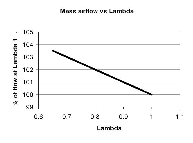


The highest flame speed has been found by research to occur at a lambda of about 0.82. High flame speed is good because it increases thermal efficiency by reducing the time available for heat to be transferred to the cylinder walls, meaning the gasses expand more, and hence make more power.
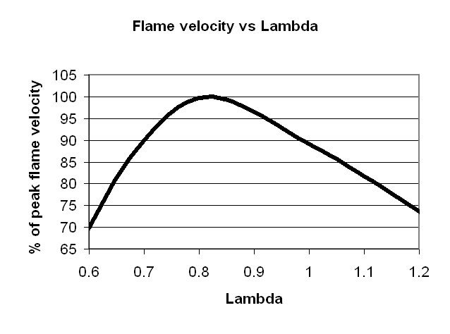


Theoretically, the highest combustion temperature occurs at the stoichiometric AFR, but in reality the highest temperature is reached at the lambda of around 0.88. This is due to thermal decomposition – and that’s about all I know about it. High combustion temperature is good because the more heat we get (assuming the engine can cope), the more expansion we get, and hence more power.
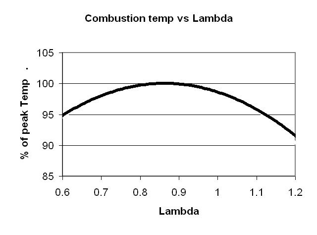


Lastly, the highest exhaust gas temperature is found at around lambda = 1.
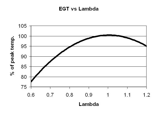


If we combine those effects, and if we consider the engine torque produced at stoichiometric to be 100%, then we can plot a lambda efficiency curve, just as we did with ignition timing.
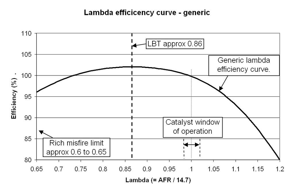


The key points are that the best lambda efficiency is at around 0.86, and this point is called the Lambda for Best Torque (or Leanest Best Torque, LBT). This is an important point to note. ADDING MORE FUEL DOES NOT GIVE YOU MORE POWER. Lambda is simply a measure of the ratio of fuel and air in the cylinder. The only way to get more power from the engine (assuming you have optimised the ignition timing) is to burn more charge - the mixture of FUEL AND AIR.

The running limits of the engine are generally around lambda 1.2 on the lean side, and lambda 0.65 on the rich side. Outside of this region combustion becomes unstable, and eventually the engine starts to misfire as there is either too little or too much fuel for stable combustion.

Lastly, the catalyst window of operation is around 0.98 to 1.02, and the fuelling must be cycled between these two values in order for the catalyst to operate correctly. This will be important if you are fitting your engine management system to a vehicle that still has to comply with catalyst emissions limits for MOT or SVA. If you want to know why and how three-way catalysts work, have a look here;

http://en.wikipedia.org/wiki/Catalytic_converter

Fuel Octane Number
We briefly touched on the RON value of fuel earlier, and I said I would explain a bit more – so here goes.

The octane rating of fuel is a measure of its knock resistance under fixed test conditions. For a description of knock, see the ignition section. The Octane Number scale is based around two known fuels – n-heptane, which was given an octane number of 0, and iso-octane, given an octane number of 100, for no other reason that these fuels were easily available in a pure form when this rating system was being developed. All other fuels are then tested using a single cylinder research engine of variable compression ratio, and compared against these two reference fuels. From these tests, the fuels octane number is derived. Note that these 2 fuels do not represent the ends of the scale – ironically n-octane has a RON of -20, and methane has RON of 120. Additives can increase this even further – US wartime aviation gasoline was commonly as high as 150 RON. Unfortunately many of these additives are either incompatible with catalysts, bad for the environment, expensive- or all three! This generally makes very high octane ‘race’ fuel a rare and expensive breed.

There are several different ways of quoting the octane number. In Europe, we commonly use the Research Octane Number (RON). However, another (and some may say more representative method) is the Motor Octane Number (MON), which provides a value under different test conditions to RON, but still using the same reference fuels. In the US, the quoted value is sometimes the roaD Octane Number (DON), also called the Anti Knock Index (AKI), which is the average of the MON and RON values of the fuels. This used to be an important distinction, since fuels of the same RON may have different MON values depending on the blend of the main constituents. Nowadays however, with increasingly stringent legislation and requirements on fuel blends for cars, the RON can generally be considered as being 10 points greater than the MON of available pump fuel, and hence the DON and AKI is halfway in between.

Here is another important point to note. RUNNING ON A HIGHER OCTANE FUEL DOES NOT GIVE YOU MORE POWER. The extra power comes from advancing the ignition timing to take advantage of the better anti knock properties. Modern OEM systems do this for you (active knock control) and most high performance engines with cylinder individual knock control are now calibrated on 100RON fuel, and the knock control system adjusts the ignition timing to allow them to run sfely on 98, 95 or even lower RON fuels. However, aftermarket systems (that I know of) still do not have this fine a level of control, and any ‘knock control’ functionality is a safeguard at best. Therefore, as I said in the Ignition section, map the car on the fuel you intend to run. If you think you might want to run different types of fuel, then you will need to map the car on each type. As we will see, this is not just ignition mapping, but affects the target lambda maps too.

Volatility
As well as all the other requirements we put on fuel, it also has to cope with changing temperatures and barometric pressures. Remember I mentioned mixing the fuel with air? Well one part of this mixing is through evaporation, or vaporisation. As we already know, gasoline is actually composed of a complex mix of fuels. Some of these will turn into vapours (gasses) at quite low temperatures. Others will remain liquid until they get quite warm. During starting the engine, the amount of airflow and hence fuel required is relatively small. This means that the physical mixing of fuel and air is less effective, since there is less charge motion to help break up the droplets of fuel and mix them with the incoming air. This is where we rely on the ‘light ends’ of the fuel to vaporise. It is this part of the fuel that starts the car – much of the rest of the fuel is wasted initially until the combustion chamber and inlet ports warm up, and we are able to increase the engine airflow. This is why we increase fuelling for cold temperatures, but we’ll cover this in more detail in the starting section.

So when the weather is cold, we need a high volatility fuel that vaporises easily to allow easy starting. The flip side of this is that when everything gets too hot, liquid fuel can turn to vapour in the fuel rail and cause a ‘vapour lock’, whereby when you open the injector you get nowhere near the amount of fuel you expect (the density has decreased dramatically). This commonly occurs after the car has been driving until warm and then stopped for 20 – 40 minutes, allowing the heat of the engine to ‘soak’ into the engine components and the fuel in the rail itself. To avoid this we need a low volatility fuel. We can also increase the starting fuel, just as we do when cold, to compensate for the reduced density effects.

To try and meet these 2 conflicting requirements fuel companies actually change the volatility of the fuel available during the year. In some countries this may be in 2 or 3 steps through the year. In the UK we normally just have winter (high volatility) and summer (low volatility) fuels.

As an aside, you’ve heard people say they left the car for a while and when they came back the petrol was ‘stale’. All that means is that the light ends have vaporised from the fuel in the tank, and left only the low volatility fuel. In extreme cases this will make starting the car difficult, but in reality there is nothing much wrong with the fuel. Mixing it 50:50 with some fresh (preferably winter) fuel will normally solve the problem (if there is one) and mean you don’t have to throw it away.

Fuel Density
Fuel does in fact change in density with temperature, significantly enough to warrant attention. The chart shows the curve that was generated for the fuel dispensing industry in order to correct the delivery of fuel pumps.
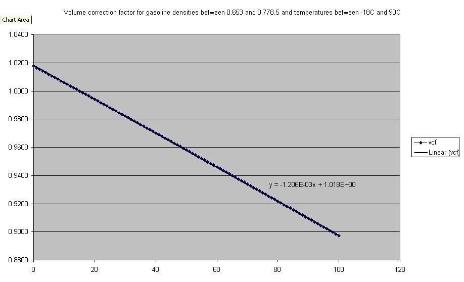


In the engine, our air fuel ratio requirement is based on mass. But injectors are flow devices. So in order to calculate the correct mass of fuel from the injector open time, we also need to know the fuel density. Or to put it another way, in order to inject the correct amount of fuel under all conditions, we need to correct the injector pulse width based on the fuel temperature, using the percentage corrections above.

Over-fuelling – why do it?
You’ll have seen tuned cars (usually turbocharged) at the track which when accelerating hard leave a trail of black smoke behind them. This is one side effect of serious over-fuelling. We can see from the theory above that we would ideally run around lambda 0.86 for peak lambda efficiency, but there are 2 good reasons for running richer than this.

Due to the high gas flow rate at high engine speeds, and under heavy loads, the exhaust components (e.g. exhaust manifold, turbo, O2 sensors) are subjected to very high temperatures. In order to keep these components at or below their temperature limits (800 to 950°C), the fuelling is increased (richened) to lower the exhaust temperatures. This happens because of the lower combustion temperature of mixtures richer than lambda 0.88, and the initial charge cooling effect of the additional fuel, as we have seen.

The very same cooling effects also reduce the chance of knock during combustion, since the in cylinder charge and combustion temperatures are lower. This is why some tuners take the approach of running extremely (some may say excessively) rich mixtures, in order to allow more spark advance, and to protect the engine components from excessive temperatures.

Personally that’s not how I calibrate engines (who wants their car to look like a diesel when they tip in?), as I feel it’s wasteful of fuel for a minimal benefit. It also increases the chances of other problems - more delivered fuel requires larger injectors, more pump capacity etc, and the excess fuel may increase bore washing effects (where the fuel literally washes the lubricating oil film from the cylinder walls), reducing piston ring and cylinder life. However, I can understand the rationale and the potential for a little more power, so if that’s the only thing that matters to you, then feel free to try it.
« Last Edit: May 25, 2007, 09:11:00 pm by cliffb75 »

Offline cliffb75

  • Global Moderator
  • Full Member
  • *****
  • Posts: 167
  • BHP: 10
Re: Calibration guides
« Reply #5 on: July 11, 2007, 06:50:59 pm »
Injecting the Fuel – Hardware.
So now we know what we are injecting, what happens to it and why. Next we need to know how to inject the stuff into our engine so we can make power.

We define the amount of fuel we require for a given amount of air as a mass. But unlike with air (using a MAF meter), we cannot easily measure the mass flow of fuel. Instead we must make some assumptions about the fuel system so that we can turn required mass of fuel per cycle into an injector opening time.

The mass of fuel delivered by the injector will depend on several things. The fuel pressure, the time the injector is open for, and the size of the injector nozzle. As usual it not that simple though.

Fuel Supply and Regulation
We’ll start with the easiest bit, the fuel pressure. In order to get accurate repeatable fuel delivery, we need the fuel pressure to be accurate and repeatable. In order to do that we need a fuel pressure regulator, that constantly controls the fuel pressure in the fuel rail to a fixed value. Most commonly these are of a returning type, whereby fuel is delivered to the rail continuously, and any excess fuel is allowed to pass through the regulator and return to the fuel tank. The pressure is regulated by a spring, which in some cases may also be adjustable. This gives good pressure control where you need it, i.e. at the injectors, but for cars with a large fuel flow requirement t full load (big power cars), if left idling for too long can steadily increase the bulk temperature of the fuel in the tank, reducing its cooling effect and hence reducing power. This is because as the fuel passes through the rail it picks up heat from the engine, and then carries this back to the tank. For things like sprint cars which wait for a bit and then go immediately into action, it might be worth considering this and switching off then engine, only running it enough to keep the oil and coolant up to temperature. This is also a good reason (other than cost) to fit copper or aluminium hardlines, that will allow heat to dissipate from the fuel as it passes the length of the car.

More modern cars are moving to return-less fuel supply systems. In this case a pressure sensor is fitted to the rail and the fuel pump speed is controlled by the ECU to deliver only the amount of fuel required to kep the pressure to target. This is mainly to enable the cars to pass increasingly tough evaporative emissions legislation. It’s not really any advantage to us in terms of making power, and just adds one more bit of complication (the pressure control system), so avoid it if you can.

In either case, something that will be critical for ensuring you keep the right pressure is the fuel pump. Firstly, make sure you get the right type. Carburettor systems run at about ½ bar of pressure. We will need more like 3 to 5 bar. When you look for a fuel pump, make sure it is one designed for an injection system, or you could get a nasty surprise!

Next you need to get one that has the capacity you require, at the pressure you intend to run. Many pumps can flow a lot of fuel, but only at very little pressure. When you load them to your required fuel pressure the flow rate can drop dramatically.


As you can see from the plot of the ubiquitous Bosch 044 pump, the flow drops from nearly 5L/min at 1 bar to about  3.5 L/min at 6bar. When selecting a pump make sure that the value you are quoted is at your intended pressure, and if it isn’t, either get more info or get a different pump.

But how do you select a pump for you engine? Let’s do an example calculation.

First you need to know what the maximum airflow of you engine will be. So assume 100% Volumetric efficiency, take the capacity of your engine (say 2L) and multiply it by your maximum RPM (say 8000rpm), divided by 2 (a 4-stroke engine only uses air every 2 revolutions remember) to give you  a mass flow in L/min.

Air Volume flow rate = VE * Capacity * Max RPM / 2
                              = 100% * 2 * 8000 / 2 = 8000L/min.

Then convert this into mass (air weighs approximately 1.2kg/m3, which is 0.0012kg/L).

Air Mass flow rate = Volume flow rate * density
                           = 8000 * 0.0012 = 9.6kg/min

Alternatively, for turbo cars, check out the flow capability of the turbo you intend to run from the compressor map. On my car I’ve selected a turbocharger that is capable of flowing around 18kg/min.

So, we now have the mass flow rate of air -, so we can calculate the required mass flow rate of fuel.

For NA engines assume a slight overfuelling from LBT – say lambda 0.8.

For turbo engines better safe than sorry, so assume quite a lot of overfuelling – say lambda 0.7.

Convert the lambda back into AFR – lambda 0.8 = 11.76:1 AFR, and then divide the airflow rate by the AFR to get the required fuel mass flow.

Fuel Mass flow rate = Air mass flow rate / AFR
                           = 9.6 / 11.76 = 0.816 kg/min

We’re nearly there now! Most fuel pump manufacturers specify the flow in either L/min or L/hour. Gasoline has a density of approximately 0.74 kg/L. So divide the Fuel mass flow rate by the density of fuel to get the Volume flow rate, and multiply by 60 to convert from minutes to hours.

Fuel Volume flow rate = Fuel Mass flow rate / fuel density
                              = 0.816 / 0.74 = 1.103 L/min
                               = 1.103 * 60 = 66 L/h
 
And there we are. We need 1.1 L/min (66 L/h) of fuel for our 2L NA. For comparison, for my turbo application, I need 2.37 L/min, or 141 L/h. In order to select a fuel pump we need to know the fuel pressure we intend to run (we’ll cover this with injectors, next), and then I would add about a 25% safety margin.

Pump volume flow rate  = Max engine flow rate * safety margin
                                       = 66 * 1.25 = 83L/h

So in the, for our example applications, we want pumps that can supply over 83 L/h (NA application) and 177 L/h (turbo application) respectively, at our intended pressure. However, one last point about fuel pressure. The fuel pressure regulator is referenced to the manifold pressure. For an NA engine, that means the delivery pressure is the same as the line pressure, since the peak plenum pressure will be atmospheric – i.e 0 gauge pressure. However, for a turbo we need to add boost pressure. So for example, if we have 1.5bar of boost above atmospheric, the delivery pressure may be 3bar, but the line pressure that the pump sees is 4.5bar. If you look back at the Bosch 044 pump chart you will see that the pump can handle it – at 4.5 bar it is capable of supplying 4L/min = 240L/h. No problems :)

Check out the link for a useful set of performance graphs and prices for suitable pumps

http://www.fuelsystem.co.uk/injection.htm


Fuel Injector Sizing
Having calculated the fuel flow requirement of the engine, we need to use the information to select suitable injectors. The ‘size’ of an injector is described by its static flow rate. That is, the flow of the injector under constant steady state conditions, running with the injector constantly open (100% duty cycle) at a known fuel delivery pressure. Typically, injector flow rates are quoted in cc/min or cc/sec.

Once again however, it is not quite that simple. In use, the injector should not be run at 100% duty cycle. This is for the same reasons as ignition coils – keeping them energised all the time makes them get hot, and then they fail. Typically injectors should be sized to deliver the maximum required flow at no more than 80% duty cycle.

So let’s take our previous example, and define the injectors we need.

We came to the conclusion that we needed to supply a maximum of 1.1L/min of fuel for the engine. We’ll assume we are using 4 injectors (1 per cylinder),

Injector flow rate  = Total engine flow rate / no of cylinders
                           = 1.1/ 4 = 0.275 L/min per injector

Then convert that to our injector flow units,

Flow in cc/min  = Flow in L.min * 1000
                       = 0.275 * 1000 = 275 cc/min

We will run a max duty cycle of 80% at this condition, so static injector flow will be (100/80 = )1.25 times this,


Static injector flow  = required injector flow * (100/ max duty cycle)
                              = 275 * (100/80) = 344 cc/min

So we need injectors capable of flowing 344cc/min.

My turbo engine example needs 741cc/min. But the injectors I have are quoted as being 720cc/min. I don’t really want to sell them and buy bigger injectors, so is there anything I can do?

This is where fuel pressure comes in. The injectors are quoted as 720cc/min at 2.5 bar delivery pressure. However, if we increase the delivery pressure we increase the static flow rate. The increase in flow with pressure is approximately as follows,

New flow  = standard flow * square root of(new pressure / standard pressure)

If we rearrange that, we can find the require pressure for our required flow

New pressure  = old pressure * (New flow / standard flow)^2    
                     = 2.5 * (740 / 720)^2 = 2.641 bar

Depending on your situation, fitting an adjustable or up-rated fuel pressure regulator, which increases delivery pressure may save you having to buy expensive up-rated injectors. In any case it will allow you to tailor your maximum injector flow to your engine requirements.

However, there are tradeoffs as usual. Firstly, there is a limit to the pressure you can run. Standard type injectors don’t like running much above 4 bar delivery pressure. That’s because with the extra pressure on them, they are much harder to open and close. This therefore takes more effort, increasing their temperature and increasing the chances of failure, and also takes longer. Secondly, increased pressure puts more strain on the rest of the fuel system – the pump and any connections. Lastly, you need to consider the minimum opening pulsewidth too.

Injector Opening Characteristics
In high performance engines, especially those which make good power at high revs or are pressure charged, the range of required fuel is large. Injectors must deliver lots of fuel at peak power and engine speed, but still be able to accurately deliver very small quantities at idle.

Fuel injectors are a solenoid operated valve. They work by energising a coil which pulls a needle off a seat, allowing fuel to flow. When the coil is de-energised, the needle is returned to the seat by a spring. Like anything mechanical injectors have mass and inertia and moving parts which create friction, which means that when the coil is energised, it takes a finite amount of time for the needle to lift from its seat and move to the full open position. During this time, the fuel flow rate is changing from zero flow to the static fuel flow rate. When the current is stopped, it takes an amount of time for the needle to return to its seat.

If we were to try and calculate the required pulse width to deliver a given fuel quantity, we would use the static injector flow rate. However, if we only energise the coil for this amount of time, we will actually get less fuel than we expect, due to the effects described. This leads to a requirement to energise the injector for slightly longer. These two times may be described as the pulse width (the electrical energising time) and the effective pulse width (calculated from the actual delivered fuel amount and static flow rate) The relationship between these two values will change according to fuel pressure, battery voltage, component temperature and the design of the injector itself.

As the pulse width gets shorter, you can see that at some point, the effective pulse width will equal zero, i.e. the energising phase will not be long enough to lift the needle off its seat enough to provide any flow. In reality this time is extended to include the energising time in which the resulting flow is unpredictable and non linear. Now here is the problem. As the injectors get bigger and / or fuel pressure is increased (static flow rate increases), then the amount of fuel delivered at the minimum pulse width is increased. We can get to a situation where we deliver too much fuel for the air we are trying to burn, and the lambda goes rich of target. This is not too much of a problem on race cars, but for road cars that need to meet emissions (either as production cars or just for MOT and SVA testing) this is a problem. This is why we don’t just spec the biggest injectors for every engine – as usual there is a tradeoff between top and bottom end performance. So the advice is to only choose the size of injector you need for your chosen power output, and this will make setting up you light load and idle region much easier
« Last Edit: January 22, 2008, 06:46:04 pm by cliffb75 »