Hello Wolf_Tm,
The top of the help page states: "0-5V analog signal can be connected to the analog input (DSub15/pin8)". As stated before connect the VDO sensor (NTC or PTC) with a pullup resistor to 5v of value which matches the sensor resistance @ 20 deg C; like this 5v --- pullup resistor --- analog1 --- VDO sensor --- GND (connecting round analog input on junction of VDO and pullup resistor).
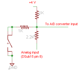
Middle of the page shows some additional info about changes to the analog input circuit in relation to round serial number, analog input 1 is shared with the button of the round.
I hope this elaboration clears things up for you.
Best regards, Dave
Yes Dave,
it clears a lot a Documentation that IMHO is confusing.
I mean... if in that page it would have been written to connect the 20°C pullup resistor to a 5v source AND to the analog input pin AND to one sensor pin (with other sensor pin to ground), I would have had no problem to understand it.
But in that page, with no explanation they were just "some additional info about changes to the circuit", you can only find this schematic for "ANALOG INPUT - serial <2900 "

where you find
- a 1K resistor to 4V (and not 5V)
- a 1K resistor to the sensor ( and not the 20°C value resistor)
- a 2.2K resistor to Analog Input
- and a wire to an "A/D coverter input" !
Sorry if i got confused by that.
Thanks