Author Topic: AFR and EGT gauge - how do you fit yours?  (Read 20974 times)

Offline cliffb75

  • Global Moderator
  • Full Member
  • *****
  • Posts: 167
  • BHP: 10
AFR and EGT gauge - how do you fit yours?
« on: January 26, 2007, 08:19:13 pm »
Last summer I lent my Impreza STi to my brother for a couple of days after he'd killed a wheel bearing in his van. Unfortunatly during the time he had it he managed to blow the engine, putting a hole through the side of the piston!

As a result, I had the engine completely rebuilt (at considerable expense). But when it came back it was boosting a lot higher than it should - to about 1.4 bar in fact when the normal boost level should be 1 bar for my model year.

So I thought I would have a look at what was happening and see if it was coping OK with the extra boost, or if something needed to be done, and to do this I chose a VEMS AFR and EGT gauge.

When the unit arrived it looked OK, but there were a couple of things I didn't like.

On the plus side its all nice an compact with long cables, which have nice protective boots on. Also the price is obviously very attractive considering the functionality. Much better value than the competition. The case and bezel are very nice, and the lens has a nice etched VEMS logo - but why is there no faceplate to cover up the PCB? I think its a real turn off for anyone wanting to install the unit permenantly in their car, as it looks untidy, and dare I say - cheap.

The other thing was the the main sensor power lead and the fuse blocks and connectors. These looked like an afterthought, with the power lead (in blue, the same as the main earth cable) running outside of the main cable to the sensor, and the fuse blocks connected with cheapo crimp connectors, which were not sufficiently insulated. Although these items are functional, it let down the product, and so I did what I usually do in these cases and started 'improving' it  ;D

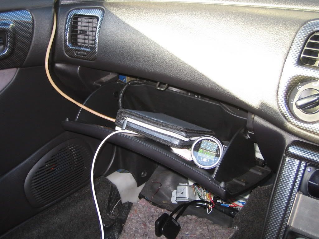
For my install I didn't need want it to be permanent, so I installed the main unit in a pod, which protects the unit and looks a bit tidier. It also allowed me to temporarily stick the gauge in my glovebox, but fixed (fairly) securely so it pointed the right way and didn't move about.

Next I extended the sensor main power feed wire and fed it up through the sheath that goes to the sensor Yes this was a pig of a job - but it worked. This meant I had just one cable running from sensor to gauge - much neater.

Beacuse the unit uses the 15 pin connector for the additional signals, you need to solder some wires on to this in order to get the signals in and out. Personally I don't see the need for this connector. Automotive stuff tends to be chunky 'electrical' wiring not that flimsy 'electronics' type stuff. I also wanted to protect those fuse blocks better.

So I mounted the whole thing in a small box with cables exiting through grommetted holes, paired off into power/ground, NB0"out/NB0" ground and rpm/boost in. In fact I hd anted to use a connector block mounted in the side of the box with standard blade terminals, but maplins didn't have any nd I couldn't be arsed to order just one by mail order  ::)

With this in place,  final touch was a bit of cable wrap to keep some of the wires bundled together, and this was the result
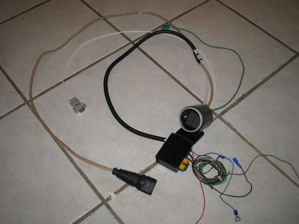


I would have run the cable wrap all the way to the gauge, but this was all I had lying about.

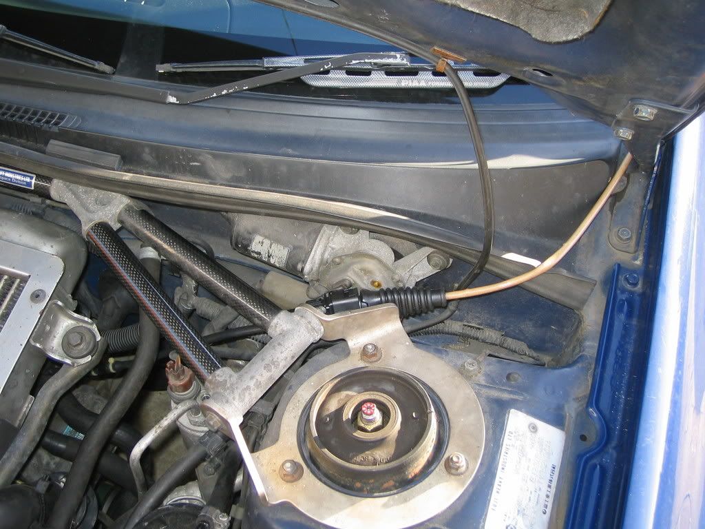
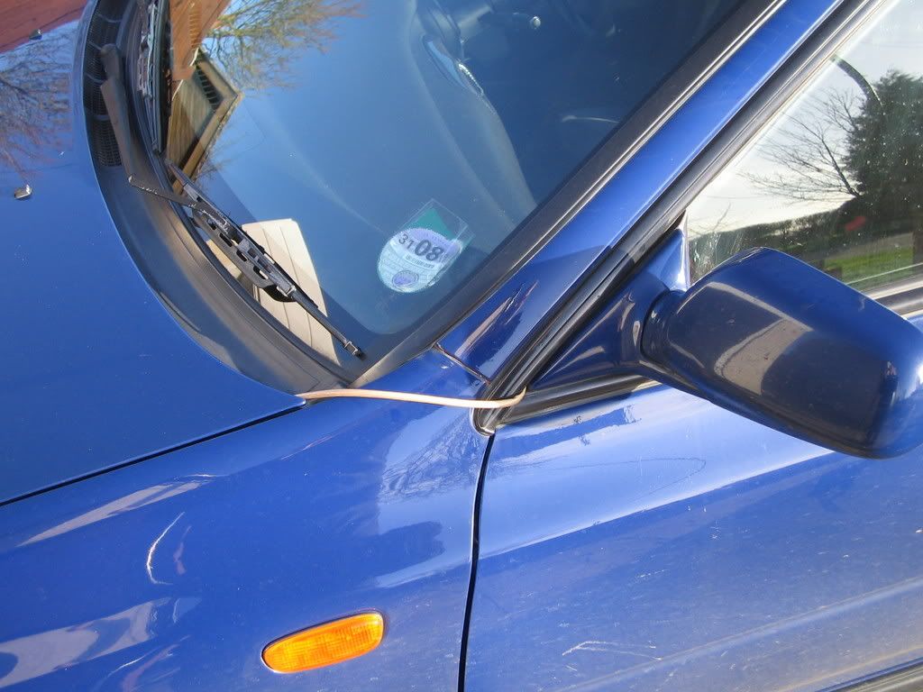
So with the unit tidied up, it was time to install it. As mentioned, I only wanted it fitted temporarily, so after a quick look at the size of the holes in the bulkhead (too small) I decided to run the cable externally and in through the door seal. A word of warning here. When it rains, water will now creep along the cable and down to the lowest point, so either make sure the cable turns up or don't go out in the rain. My glovebox ended up a bit damp.........


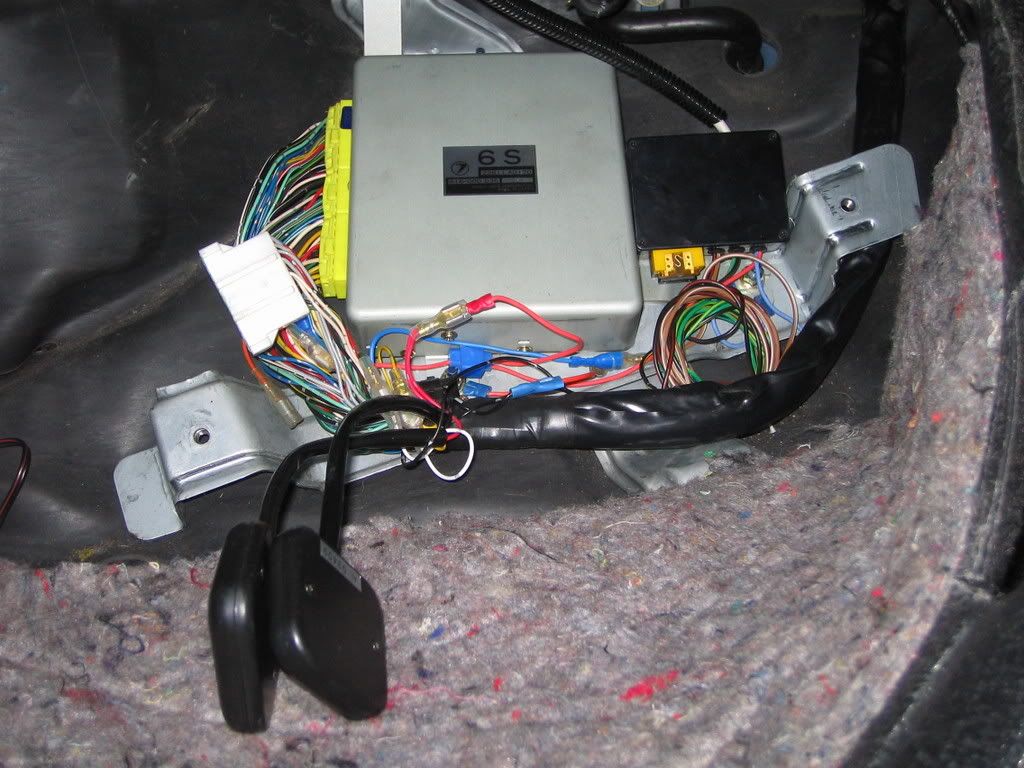
I had to pull the ECU cover off in order to get to the loom anyway (to install the HKS AFR and FCD - I know they're bodge devices but they suit my purposes for now) and so I mounted the box down here also. This made it easy to tap into the lamda sensor signal (to feed the NB02 output into the ECU) and pick up the rpm and boost signals if I wanted to. I then took the power feed from the main ECU feed so that the gauge came on and off with the main relay. Finally the gauge itself was mounted in the glovebox with some double sided pads, et voila a temporary install. (Please excuse the dodgy crimp connectors - i ran out of nice ones at this point but wnated to get it finished so used what I had about the place. Oh the shame.... :-[)


A couple of hours of thrashing about then confirmed my fears - the fuel system was not keeping up with the boost being achieved. The engine would hold about 0.88 lambda from 1 to 1.2 bar, but then lean off up to lambda 1 at 1.4 bar. Not good at all. This makes me think its actually getting to the limit of the injectors, but it may have just fallen off the end of the map. Either way, it needed sorting, so back to the house.

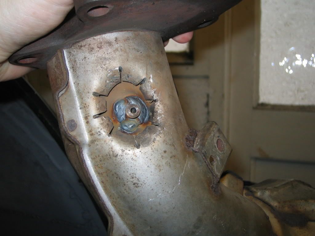
In the process of testing this, the exhaust fell off. Well, not off exactly, but it split one of the welds on the downpipe. This meant I hd to remove the downpipe and re-weld it, so while it was off I took the opportunity to add an EGT boss. Its post turbo, so only of limited use, but at least gives a better indication of whats heppening than no EGT at all.


I then trawled the web and discovered my problem was most likely the boost control solenoid having got full of oil when the piston went, and not operating properly. A bit of time spent with brake cleaner along the signal pipes and through the valve, and it did indeed sound like it was working better (the clicking from the valve was more pronounced, and not dull like when I started cleaning it.

So with it all back together off I went for another few hours of testing, and sure enough problem solved. Boost back to sensible levels (about 1.1 bar at 4000rpm dropping back to 1bar at 5000 and holding to the redline) and fuelling about 0.88 lambda. Post turbo EGT's never got past 550C, and it was interesting to see that under normal cruising conditions they tend to be about 300C, which is a bit on the cold side for catalysts to work.

So that was that. The units now back out again until I either use it for the minor or install VEMS in the Scoob. Which will happen first I wonder??

Offline Tony C

  • Hero Member
  • *****
  • Posts: 650
  • BHP: 8
    • Capriracing
Re: AFR and EGT gauge - how do you fit yours?
« Reply #1 on: January 26, 2007, 08:36:55 pm »
i have done something similar with the blue cable, (being part time auto electrician at work got my hands on all sorts of stuff  ::))

once mines all finished and installed will post a pic,

Vems Ecu, Twin Plenum efi and N2o
13.314 @ 104.39 mph (10/06/07 3.9 v8)
Sponsored by: www.caprisport.com & www.interpart.biz
Web site: http://www.capriracing.co.uk

Vems Firmware: V1.1.74

Offline dnb

  • Global Moderator
  • Hero Member
  • *****
  • Posts: 837
  • BHP: 19
Re: AFR and EGT gauge - how do you fit yours?
« Reply #2 on: January 27, 2007, 03:16:02 pm »
Cliff - what model year Scoob?  I guess it's MY97 from the photos - so it's got the silly ECU you can't do much with...

I'm working on a loom adaptor for my MY96 UK turbo (and will then move on to my MY99 STI if all goes well) so VEMS could soon be plug and play for Scoobs :D  Just need Rob to send me those connectors ;)  Maybe one of these would suit your purposes?

I noticed the Griff EGT was in the low 300s on cruise too - but no cats to worry about at the moment.   

When you VEMS the Scoob, I hope you replace the 2 port wastegate control solenoid with something better than a nasty "controlled leak" device.  I found that when my STi was ECUTek'd with a 3 port solenoid, it was MUCH happier - and survives 1.4 bar quite nicely now.

Offline cliffb75

  • Global Moderator
  • Full Member
  • *****
  • Posts: 167
  • BHP: 10
Re: AFR and EGT gauge - how do you fit yours?
« Reply #3 on: January 27, 2007, 09:41:54 pm »
Cliff - what model year Scoob?  I guess it's MY97 from the photos - so it's got the silly ECU you can't do much with...

I'm working on a loom adaptor for my MY96 UK turbo (and will then move on to my MY99 STI if all goes well) so VEMS could soon be plug and play for Scoobs :D  Just need Rob to send me those connectors ;)  Maybe one of these would suit your purposes?

I noticed the Griff EGT was in the low 300s on cruise too - but no cats to worry about at the moment.   

When you VEMS the Scoob, I hope you replace the 2 port wastegate control solenoid with something better than a nasty "controlled leak" device.  I found that when my STi was ECUTek'd with a 3 port solenoid, it was MUCH happier - and survives 1.4 bar quite nicely now.

You like your toys don't you  ;D

You guessed right. MY97 ver3 sti, complete with silly ECU  ::)

Thing is I already have a project, so fitting the VEMS to the scooby would be a 'bit on the side', and I would eventually move the ECU into the Minor, hence I want to be able to swap back to standard as required, and that means using all standard sensors and actuators, as well as a conversion loom. Also being a silly ECU its a 3 plug version, so will need to make a different conversion loom from yours (I think?)

Problems as I see it are the AFM, purge and maybe AC (not sure if this is an input or output pin). Also the triggering off the standard tooth patterns, although I understand we may now have a solution to that (your work?). Any more problems you can think of?

For the conversion loom I would want to go for a breakout for a wideband lambda sensor, so maybe a better boost solenoid could be added that way. Easy enough to swap some pipes back and forth if required. AS for AFM, I'm not sure why VEMS doesn't seem to support them? Is it just not knowing the characteristics or is there something clever in the control of the hotwire current or something like that? I guess I could leave it diconneted (problems with the wire getting dirty if not heated?) or remove it when on VEMS - again not a biggy to bolt back in if required. But just ECU and lambda sensor swap would be the nicest.

I'd be interested to hear you experience and opinions  :)

And out of interest did you have it dyno'd at 1.4 bar? What figures did you get?

Offline dnb

  • Global Moderator
  • Hero Member
  • *****
  • Posts: 837
  • BHP: 19
Re: AFR and EGT gauge - how do you fit yours?
« Reply #4 on: January 27, 2007, 10:50:28 pm »
Not dyno'd the STi, but worked out with accelerometer to somewhere around 320 to 330bhp.  Not too bad for a near-standard engine.  The MY96 is a car-without-a-shell after it was written off.  I'm slowly designing and building a light weight chassis for it based on TVR concepts.  It's back of the queue at the moment, but I do have a couple of people wanting their Scoobs mapped.

I don't remember if the MY99 and MY97 connectors are physically the same or not.   They are certainly different to the MY96, so I suspect I need 3 versions of the loom converter.

The trigger is nothing to do with me - someone noticed that the Subaru trigger was very similar to the Fiat Stilo trigger!  Not had chance to play yet as the Griff is eating all the time.

AC isn't a problem - the ECU input seems to only be used to raise the revs at idle and the output can be "simulated" with a misc out.

Purge is a bit of a sticking point, as no-one (despite my naggings and half-baked algorithm ;) ) has implemented a purge solenoid output in the stable firmware...

AFM - again, not really a problem as I don't much like the MY99 AFM from a reliability point of view, so I'd rather be without it.  MAP based works fine for me (and for Link & John Banks "MAF Sim" Power FCs), and the Subaru has a decent enough MAP sensor...  Amongst the VEMS developers, MAF seems to be a bit of a dirty concept.
I plan to remove it and use a straight piece of pipe so it isn't damaged although I beleive this to be unlikely given how far forward in the intake it is.

The conversion loom would certainly have a breakout - it would include WBO2, air temp and knock sensors (on the MY96 the knock sensor is single-wire and picks up noise like you wouldn't believe) Maybe 2 knock sensors so games can be played ;)

« Last Edit: January 27, 2007, 10:52:51 pm by dnb »

Offline Tony C

  • Hero Member
  • *****
  • Posts: 650
  • BHP: 8
    • Capriracing
Re: AFR and EGT gauge - how do you fit yours?
« Reply #5 on: April 10, 2007, 09:33:02 pm »
i have nearly finished the install of mine,
here is the drivers manifold, the egt sensor is fitted in number 3 primary pipe and the wideband sensor at the bottom of the down pipe:


i will post the pics of the gauge install the weekend,

is there two different wire lengths for the wb02 senors?
as the one that came with the egt is longer and is better for my installation (would of been easier for me if the ecu came with that longer one)

also i did have a post regarding this i think but now can't find it, whats the little silver button for on the front of the egt gauge?

Vems Ecu, Twin Plenum efi and N2o
13.314 @ 104.39 mph (10/06/07 3.9 v8)
Sponsored by: www.caprisport.com & www.interpart.biz
Web site: http://www.capriracing.co.uk

Vems Firmware: V1.1.74

Offline rob@vems.co.uk

  • Hero Member
  • *****
  • Posts: 3115
  • BHP: 49
    • VEMS Forum
Re: AFR and EGT gauge - how do you fit yours?
« Reply #6 on: April 11, 2007, 12:14:52 am »
is there two different wire lengths for the wb02 senors?
as the one that came with the egt is longer and is better for my installation (would of been easier for me if the ecu came with that longer one)

also i did have a post regarding this i think but now can't find it, whats the little silver button for on the front of the egt gauge?

Alas there was a shortage of sensors at the begining of the year and the only ones we can get now have a shorter length cable :(

The button steps through the display modes:

 0: internaltemp_C   Lambda
 1: internaltemp_C   AFR
 2: EGT degC      Lambda
 3: EGT degC      AFR
 4: internaltemp_F   Lambda
 5: internaltemp_F   AFR
 6: EGT degF      Lambda
 7: EGT degF      AFR
 8: MAT degC      Lambda
 9: MAT degC      AFR
 10: RPM      Lambda
 11: RPM      AFR
 12: MAT degF      Lambda
 13: MAT degF      AFR

Offline Tony C

  • Hero Member
  • *****
  • Posts: 650
  • BHP: 8
    • Capriracing
Re: AFR and EGT gauge - how do you fit yours?
« Reply #7 on: April 14, 2007, 09:52:41 pm »
cheers mate,
my ecu came last yr with a short sensor lead,
my egt came later with a longer lead :)

Vems Ecu, Twin Plenum efi and N2o
13.314 @ 104.39 mph (10/06/07 3.9 v8)
Sponsored by: www.caprisport.com & www.interpart.biz
Web site: http://www.capriracing.co.uk

Vems Firmware: V1.1.74

Offline Richy_Boy

  • New Users
  • *
  • Posts: 1
  • BHP: 0
Re: AFR and EGT gauge - how do you fit yours?
« Reply #8 on: April 15, 2007, 09:54:55 pm »
Just bought one of these gauges so that I can better map my LPG setup in my car... which makes the EGT sensor especially useful due to the hotter burning temps of Propane.

Anyway, thanks for the info posted, I'm absolutely bricking it now about fitting it... it looks a bit complicated - and that connector plug, no way in hell will fit through my bulkhead  :'(

Cheers chaps,

Rich
----------------------------------------
Richy_Boy - Dual fuel Nissan200sx S14a

Offline Denmark

  • Hero Member
  • *****
  • Posts: 542
  • BHP: 7
Re: AFR and EGT gauge - how do you fit yours?
« Reply #9 on: April 19, 2007, 04:36:18 pm »
Cliff,

Are you sure that your fuelpump is ok, i would say that the fueling is awfull lean, and not anything the the Impreza like´s , i predict that it will make the same hole in the piston, if nothing is being done,
You need to make it aleast lambda 0,8 and no leaner then that!.

/Skassa


working on the boxer

Offline cliffb75

  • Global Moderator
  • Full Member
  • *****
  • Posts: 167
  • BHP: 10
Re: AFR and EGT gauge - how do you fit yours?
« Reply #10 on: April 19, 2007, 10:26:07 pm »
Hi Skassa

I think fuelpump is fine.

The problem was actually that it was overboosting after the rebuild, and I didn't know why. I bought the wideband and EGT to see if it could live with the extra boost - it can't.

A quick search of the forums suggested I clean the boost lines and boost solenoid, and sure enough this got everything back under control.

The reason it melted in the first place was because the MAF to compressor in pipe had split, which I believe was allowing the turbo to draw in more unmetered air so it was running lean and advanced - not a good combination.

Everything back to standard now and quite happy  :)

However, if anyone else reading this has a standard JDM Impreza STi and wants to do a couple of WOT lambda logs, I'd be interested to see the results and compare them to mine. I've even got a wideband unit you could use  ;D

Offline dnb

  • Global Moderator
  • Hero Member
  • *****
  • Posts: 837
  • BHP: 19
Re: AFR and EGT gauge - how do you fit yours?
« Reply #11 on: April 20, 2007, 10:12:54 am »
I do have a JDM Impreza, but it's not exactly standard...  Happy to help you gather some data at some point :)

Offline Denmark

  • Hero Member
  • *****
  • Posts: 542
  • BHP: 7
Re: AFR and EGT gauge - how do you fit yours?
« Reply #12 on: April 20, 2007, 04:15:48 pm »
I have made a few Impreza´s here in denmark,
But not a standard STi, but i have never had one in my hands that run lambda 0,88 at WOT,
I´m pretty sure , that if the car is "used" , there will be a new hole!

The ones i have made are all my99-00 and only a few newage, but they all seem to be around 10AFR when WOT, and that´s the standard setting then you can lean it out to around lambda 0,78 or there about.

When i first got the Impreza in year 2000, i had a company here in Denmark map a LinkECU for me, they were used to making Vw, and they mapped it to run lambda 0,85.
That lasted okay for road use, but the first time i had in on a trackday ,i burned a huge hole in number 4 piston,
So i learned the hard way, as i did that one more time :(
Then i learned to map it myself, a pararel fuel delivery mod to , fix the running lean, and lots of other parts.

But the main problem was that it was underfueling, when it first got mapped,
The car have now run around 100k km, with just under 400hp, with nothing being done other then oilchange!.
That´s what i call reliebel (cant speel that   :D)


/Skassa
working on the boxer

Offline cliffb75

  • Global Moderator
  • Full Member
  • *****
  • Posts: 167
  • BHP: 10
Re: AFR and EGT gauge - how do you fit yours?
« Reply #13 on: April 20, 2007, 07:05:01 pm »
I have made a few Impreza´s here in denmark,
But not a standard STi, but i have never had one in my hands that run lambda 0,88 at WOT,
I´m pretty sure , that if the car is "used" , there will be a new hole!

The ones i have made are all my99-00 and only a few newage, but they all seem to be around 10AFR when WOT, and that´s the standard setting then you can lean it out to around lambda 0,78 or there about.

When i first got the Impreza in year 2000, i had a company here in Denmark map a LinkECU for me, they were used to making Vw, and they mapped it to run lambda 0,85.
That lasted okay for road use, but the first time i had in on a trackday ,i burned a huge hole in number 4 piston,
So i learned the hard way, as i did that one more time :(
Then i learned to map it myself, a pararel fuel delivery mod to , fix the running lean, and lots of other parts.

But the main problem was that it was underfueling, when it first got mapped,
The car have now run around 100k km, with just under 400hp, with nothing being done other then oilchange!.
That´s what i call reliebel (cant speel that   :D)


/Skassa

Interesting.

Remember though that holes in pistons are caused by excessive combustion temp and pressure, and thats normally (mainly) due to excessive ignition advance (for the conditions) causing det, rather than lean running. I know running lean contributes too - I'm just pointing out that there is more to melting a piston than just the fuelling.

In your example you also need to consider if the additional heat (both to coolant and inlet air temperature) from running the engine harder on the track than the road meant that you were effectively running too much advance for the charge the engine was receiving. This is even more likely if the company mapped it by running repeated runs and never let the temperatures get too high, and so never included any ignition or fuelling compensation for this condition.

For example I've also mapped a few Audi 1.8T engines. In some setups we could run 0.85 no problem. In other cases (more boost, less efficient intercooler) we ran down to lambda 0.78 as we needed to retard the ignition so much to avoid det, which in turn incresed the EGT's. These engines were mapped on an engine dyno at steady state conditions, so that everything was fully heat soaked and at a stable temperature. That means when we put it in a car it is very difficult to get it that hot (at most places you cannot hold WOT for 2-3 minutes), so everything was safe.

Once you get past about lambda 0.86 you are past the max torque fuelling point. At that stage any extra fuel is purely there mainly to reduce EGT's.

And once you get richer than about 0.82, wideband lambda sensors are not so accurate (unless you have had them calibrated)

Anyway - I take your point. It is possible that it is running lean, and that is due to the fuel pump. Its just I have no sata for a standard car to make a comparison against. I'll see if I can get a pressure sensor form work and take a fuel pressure log, and then I guess we'll find out. :)


Offline cliffb75

  • Global Moderator
  • Full Member
  • *****
  • Posts: 167
  • BHP: 10
Re: AFR and EGT gauge - how do you fit yours?
« Reply #14 on: April 20, 2007, 09:01:42 pm »

is there two different wire lengths for the wb02 senors?
as the one that came with the egt is longer and is better for my installation (would of been easier for me if the ecu came with that longer one)


Bosch supply the sensors with a myriad of lead lengths for different customers. I Had a word with someone I know  ;) about this, and for people who want a long lead, the "Bank 1" sensor on the Audi A8 of a couple of years back came with a 1210 mm lead, part no 077 906 265 AC. You will probably need to pay through the nose though.........

 :)