Author Topic: RS13 - CA18DET Wiring  (Read 12663 times)

Offline Maff

  • Jr. Member
  • **
  • Posts: 8
  • BHP: 2
    • Kardiak
RS13 - CA18DET Wiring
« on: March 05, 2007, 09:30:21 pm »
Picked up my gauge from Rob on Wednesday at the bigpower.co.uk meet :) Cheers mate. And this evening was the first chance id got have a proper play.

Fought my way through the wiring diagrams and it looks as this is the way to do it for a CA in an S13.

Wideband 15 pin Plug to CA Ecu wiring:

RPM Signal - Wideband digital signal Pin 10 ----> Ecu pin 7 - Splice into Yellow wire with Red stripe
AFM Signal - Wideband analogue signal Pin 8 ----> Ecu Pin 27 - Splice into Green wire with Black stripe
Lambda Out - Wideband out Pin 1 ----> Ecu Pin 29 - Cut white wire for narrow band signal replace with this
Lambda Ground - Wideband ground Pin 9 ----> Ground

Live Wideband ----> Stereo Blue wire (or any non permanent live, but this is good for me as i dont have one)
Ground Wideband ----> Ground

Hopefully ive got that all right, Saturday will tell, quick question though, why the extra lambda ground? isnt a ground a ground a ground? My electronics knowledge is sadly lacking :(

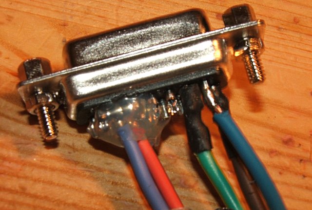
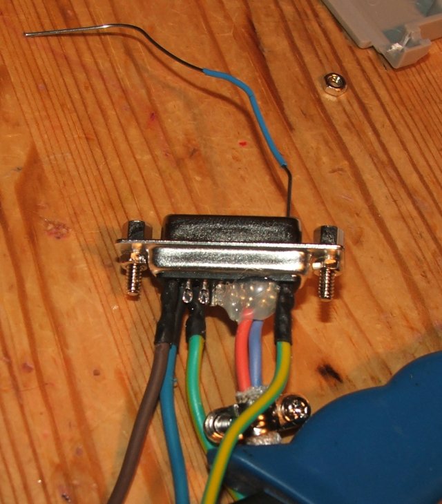
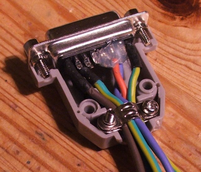
Wired up the extra feeds:


Think ill follow cliffs idea and pop the components in a little box too, as i too will be moving it from car to car.

So with any luck it should all be up and running at the weekend and with RPM and AFM in... im half way to getting a live trace in my CA18DET ECU editor, woop!

Offline rob@vems.co.uk

  • Hero Member
  • *****
  • Posts: 3115
  • BHP: 49
    • VEMS Forum
Re: RS13 - CA18DET Wiring
« Reply #1 on: March 05, 2007, 09:43:30 pm »
Hopefully ive got that all right, Saturday will tell, quick question though, why the extra lambda ground? isnt a ground a ground a ground? My electronics knowledge is sadly lacking :(

Grounds for sensors can quite often be biased above 0v to help reduce noise.  If you have a seperate ground to your sensor then you're best to use the gauge's one.

Offline Anu

  • Jr. Member
  • **
  • Posts: 3
  • BHP: 0
Re: RS13 - CA18DET Wiring
« Reply #2 on: March 19, 2008, 10:51:12 am »
I'm gonna connect the wideband also to a 200sx RS13, to a standart ECU with a HD stage 1 chip.
When i look at the wiring diagram on the help page, Pin 11 would need to be connected to the 12v feed through a resistor? I dont see it in the picture above, is this not nescessary when connecting it to a 200sx?
If it is needed, what resistor should I use? Is the resistor needed to "align" the RPM signal?

( Pardon my englisch ;) must be horrible for you to read :P)

Offline Maff

  • Jr. Member
  • **
  • Posts: 8
  • BHP: 2
    • Kardiak
Re: RS13 - CA18DET Wiring
« Reply #3 on: March 19, 2008, 11:13:40 am »
The resistor is needed, I have mine soldered to the spliced wire on the ECU, without it the car the VEMs will cause the car to stall when you connect up. Im sure Rob will explain why  ;)

Offline rob@vems.co.uk

  • Hero Member
  • *****
  • Posts: 3115
  • BHP: 49
    • VEMS Forum
Re: RS13 - CA18DET Wiring
« Reply #4 on: March 19, 2008, 11:40:27 am »
I'm gonna connect the wideband also to a 200sx RS13, to a standart ECU with a HD stage 1 chip.
When i look at the wiring diagram on the help page, Pin 11 would need to be connected to the 12v feed through a resistor? I dont see it in the picture above, is this not nescessary when connecting it to a 200sx?
If it is needed, what resistor should I use? Is the resistor needed to "align" the RPM signal?

( Pardon my englisch ;) must be horrible for you to read :P)

As Maff says the resistor is needed.  The reason is that the Gauge has a reference voltage of a couple of volts which is used to stabilise the voltage reading and stop noise and other problems.  The trouble is that this voltage causes the Maff voltage to increase  - which fools the ECU into thinking that more air is flowing through the sensor - so it adds more fuel and you get to run really rough.

Offline Anu

  • Jr. Member
  • **
  • Posts: 3
  • BHP: 0
Re: RS13 - CA18DET Wiring
« Reply #5 on: March 20, 2008, 08:44:01 am »
To be sure, im using the Wideband gauge just for logging and keeping an eye on my mixture, im not feeding the data from the gauge back to the ecu, since im using a stock ecu with a piggyback fuelcomputer, the only connection there is with the gauge and the ECU is to get the RPM signal to the gauge, for logging purposes.

Im talking about this image:


Should i put a resistor also on the RPM feed (pin 10)? and what value should it be?
And what value resistor should i put between pin 11 and the 12v line?

Offline rob@vems.co.uk

  • Hero Member
  • *****
  • Posts: 3115
  • BHP: 49
    • VEMS Forum
Re: RS13 - CA18DET Wiring
« Reply #6 on: March 20, 2008, 09:12:11 am »
Start off without the resistor, if you get problems with noise (which will show as an incorrect RPM signal) then we can play with resistor values.  The Nissan Tacho signal is a solid square wave with a good voltage so IIRC it doesnt need the resistor.

Offline Anu

  • Jr. Member
  • **
  • Posts: 3
  • BHP: 0
Re: RS13 - CA18DET Wiring
« Reply #7 on: March 20, 2008, 01:20:52 pm »
Ok cool thnx :), ill try it sometime next week probably, first have to get the revised engine running correctly :P